Rebooting the Use Case Diagram
Use cases have fallen out of favour in recent times with user stories becoming the preferred way for teams to manage requirements. For a good discussion of the differences, see Gustav Bergman’s older (but still relevant post) A Use Case is to a User Story as a Gazelle is to a Gazebo. In the rush away from use cases, everyone seems to have forgotten Use Case Diagrams. Actually, there is a fairly tenuous link between a use case diagram and the often excruciatingly detailed scenarios that many people associate with use cases. Zicomi’s UML Online Dictionary defines a use case as:
an interaction between the actors and the entity (most commonly a system) that is modelled. They always describe an observable piece of value as seen from the actor’s point of view
The definition goes on to describe the detailed scenarios that we are more familiar with:
as with all UML elements “behind” the graphical representation is a descriptor. In the case of the use case this descriptor forms the larger part of the definition of the use case
If we forget the descriptor part of the definition and just think about the graphical representation, it becomes fairly obvious that we could use a use case diagram to depict use stories without breaking any “rules” or introducing unnecessary complications. This is exactly what I teach students to do in my courses.
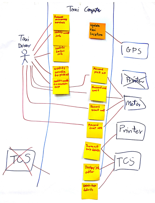
Teams usually have a preference for visual tools when they collaborate. Use case diagrams are still one of the best ways I know of showing software features on a diagram. When I draw a use case diagram on a whiteboard (or construct one using sticky notes), I like to rethink some of the standard terminology. For me, the all important bounding box on the diagram represents a component. Rather than use actors, I prefer to think in terms of personas to describe the people that interact with the component. For some practical advice on personas see Raven Veal’s post How to Define a User Persona? I retain the stick figure actor symbol for personas but prefer rectangles for external components. (For those that remember, I also thought it was ludicrous to represent things like web servers as stick figures). 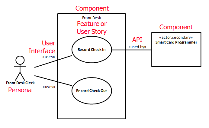 Rather than
use cases, I think of the elliptical shapes inside the bounding box as representing features (or user stories if the team prefers). I don’t follow any rules about how big or small the feature can be. Anything from an epic feature such as Manage all aspects of the hotel all the way down to a fragment of functionality such as Search for guest is quite acceptable. The only aspect that is non-negotiable, is that the feature must be named using an active verb-noun phrase. For more on naming features see my previous article Describing Software Features. The line connecting a persona to a feature represents the way in which a persona uses the component. Another way of thinking about the connecting line is that it represents a user interface. Many misunderstand the line to mean that there is a flow of information and add an arrow to one, or both ends of the line. I have lost count of the number of times I
have said, “use case diagrams are NOT data flow diagrams”. External components either use a feature or are used by a feature, depending on whether:
Rather than
use cases, I think of the elliptical shapes inside the bounding box as representing features (or user stories if the team prefers). I don’t follow any rules about how big or small the feature can be. Anything from an epic feature such as Manage all aspects of the hotel all the way down to a fragment of functionality such as Search for guest is quite acceptable. The only aspect that is non-negotiable, is that the feature must be named using an active verb-noun phrase. For more on naming features see my previous article Describing Software Features. The line connecting a persona to a feature represents the way in which a persona uses the component. Another way of thinking about the connecting line is that it represents a user interface. Many misunderstand the line to mean that there is a flow of information and add an arrow to one, or both ends of the line. I have lost count of the number of times I
have said, “use case diagrams are NOT data flow diagrams”. External components either use a feature or are used by a feature, depending on whether:
- the feature provides a service for example, a cloud based server that is used by a mobile app to Sync contacts; or
- the feature requires a service for example, a web browser that uses a web server to Display web page.
In either case the line connecting the feature to the external component represents an API. This brings me to my final point on case diagrams. Most of the examples I see are quite frankly ridiculous. Missing bounding boxes (who is using what?), arrows on one or both ends of a connector (one more time, “its not a data flow diagram”) and a “birds nest” of criss-crossing lines that totally obscures any possible meaning the author intended. There are many approaches to fixing these problems, such as drawing two or more diagrams to eliminate crossing lines. You can find more tips and tricks to improve use case diagrams in this SlideShare [slideshare url=“https://www.slideshare.net/lonsdalesystems/use-case-diagrams-tips-and-tricks-117018831”] The approach to use case diagrams that I have described is well aligned with the Requirements Discovery Canvas . Inspired by the Business Model Canvas, the Requirements Discovery Canvas provides a framework for collaboration leading to shared understanding, that can be used by both agile and traditional software development teams. 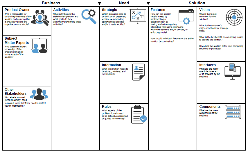 Used together, use case diagrams and the Requirements Discovery Canvas provide visual tools that help teams discover and organise software features that will ultimately become the product backlog. The canvas already includes sections for features, components, user interfaces and APIs, so it is a simple matter to populate the canvas from use case diagrams that teams drawn to explore their options and better understand the relationships between features. This shared understanding helps to
ensure that the product backlog does not become an unruly wish list of disparate features.
Used together, use case diagrams and the Requirements Discovery Canvas provide visual tools that help teams discover and organise software features that will ultimately become the product backlog. The canvas already includes sections for features, components, user interfaces and APIs, so it is a simple matter to populate the canvas from use case diagrams that teams drawn to explore their options and better understand the relationships between features. This shared understanding helps to
ensure that the product backlog does not become an unruly wish list of disparate features.
 Rebooting the Use Case Diagram