The UML Collaboration Element
Suppose I want to conceptually model a network of flights between airports. No problem I use a class called Airport and a recursive association called Flight. A recursive association is one that connects two instances of the same class. In other words both ends of the association touch the same class. Both ends of the association have 0..* multiplicity.
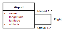
Most conceptual modellers will instantly recognise that this model fragment represents a network. Now the fun starts! Where do I put the attribute for the flightNumber of a flight? The problem is that I can’t capture this attribute in the basic network model.
OK. I introduce a second class called Flight and have two associations between Airport and Flight. One association is called Depart and the other is called Arrive. The Airport end of both associations has a multiplicity of 1 and the Flight ends a multiplicity of 0..* (closed or airports under construction do not have flights).
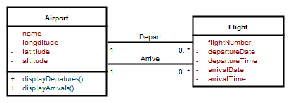 Many conceptual modellers will still recognise this as a network. Now where do I put the operation to display arrivals and departures. Airport? Possibly. I would need displayArrivals() and displayDepartures(). But what about transit airports? I don’t want to display these on my arrivals or departures boards. OK I could add another association between Airport and Flight called Transit. Getting messy! What about another association for alternate airports for flights that are diverted etc etc.
A better approach is to create an abstract class AirportRole with an operations displayFlights(). This class has an association with Airport and Flight. It also has three specialised (sub-)classes Depart, Arrive and Transit. These specialised classes all inherit the displayFlights() operation but implement it differently.
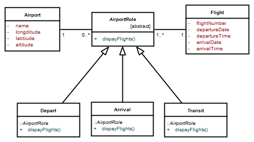
If I tell Depart to displayFlights() it displays departures, if I ask Arrive to displayFlights() it displays arrivals, if I ask Transit to displayFlights() I get an error. This is called polymorphism.
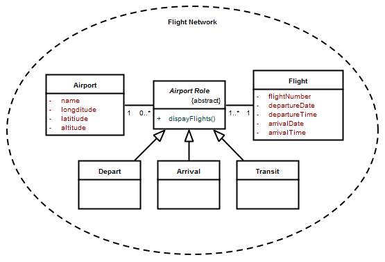
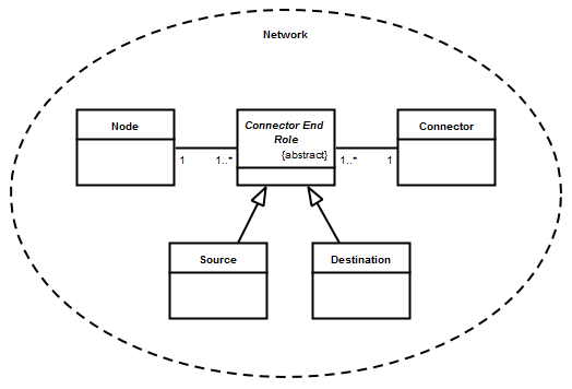
However, very few conceptual modellers would now instantly recognise this as a network. Enter the collaboration element. If I create a collaboration element, label it Flight Network it becomes perfectly obvious that we are dealing with a network.
 A generalised model of a network consists of nodes and connectors. Each connector connects two nodes. In a directed network, the connector has a source node and a destination node. The direction of the connector is from the source node to the destination node.
You can learn more about conceptual modelling using the UML in our Requirements Analysis course
 The UML Collaboration Element